

What Happens When the OBD-II Port Itself Is Damaged
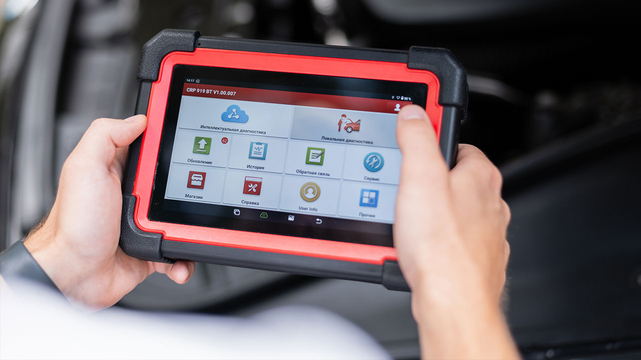
Every tech knows the routine. Key on, scan tool in, pull codes, start diagnosing. It is one of the most repeated steps in any shop, and it works so consistently that most techs never think twice about the port itself. Until the day the scan tool powers up, shows no communication, and nothing else makes sense.
Over 80% of OBD-II communication failures stem from physical hardware issues, not software or protocol problems. The scan tool is usually fine. The modules are usually fine. The problem is in the connector, the wiring behind it, or both. And unlike a blown fuse or a bad module, a damaged DLC connector is one of the most overlooked causes of a no-communication condition because most techs never consider the port itself as the failure point.
What the OBD-II Port Actually Is
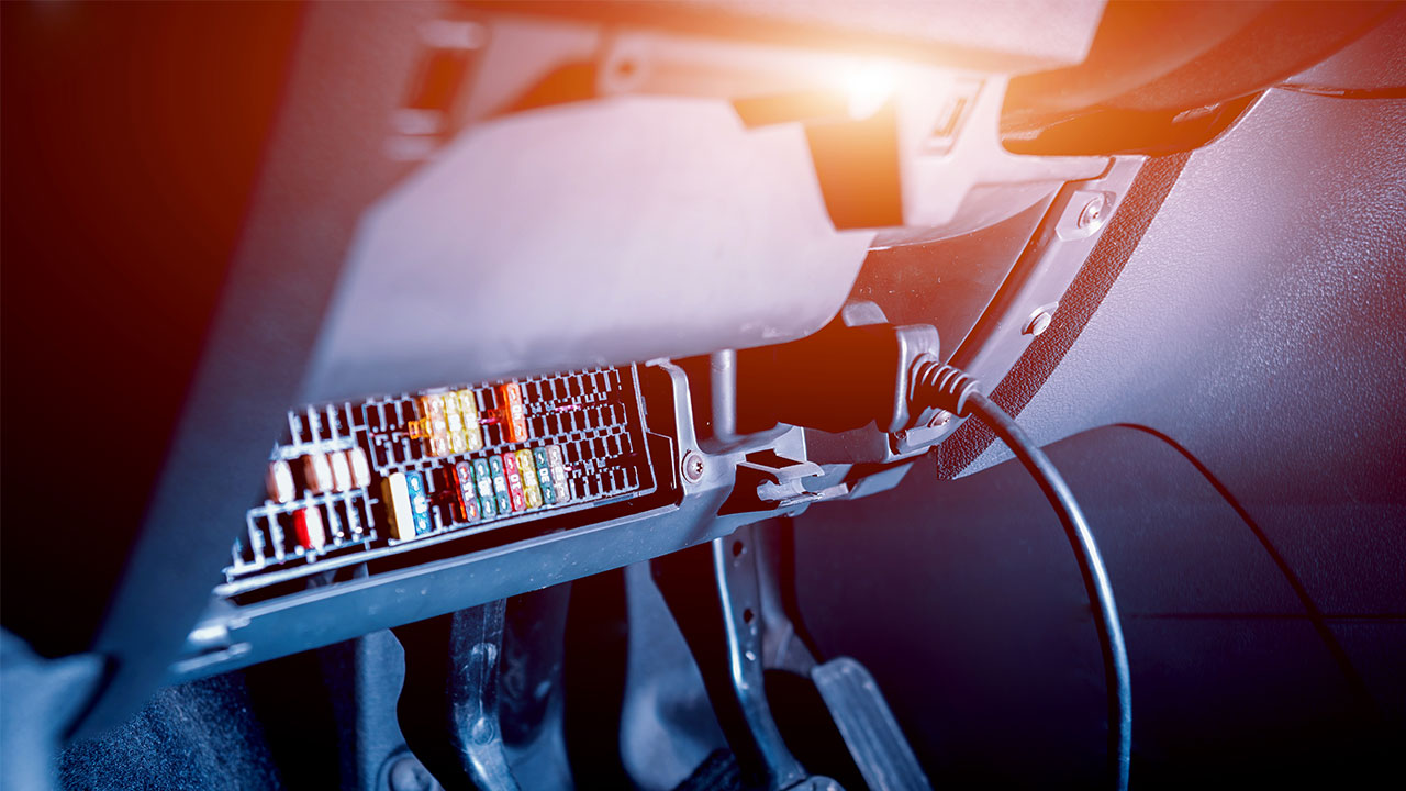
The Data Link Connector, or DLC, is a 16-pin automotive electrical connector standardized under SAE J1962. Every vehicle sold in the U.S. since 1996 has one. It is more than just a location where a scan tool plugs in. The pins inside are where the technician accesses serial data networks, power, and signal grounds. Pin 16 carries battery voltage. Pins 4 and 5 are chassis and signal ground. Pins 6 and 14 are the CAN high and low lines that carry the actual diagnostic data between the scan tool and every module on the network.
When any one of those connections is compromised, the entire communication chain breaks down. A tech who chases a no-communication code without first inspecting the DLC is working backward.
How the DLC Gets Damaged
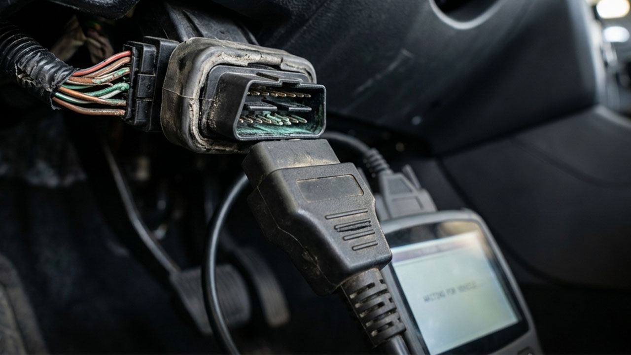
The OBD-II port sits under the dash, close to the driver's knee, which puts it at risk of physical abuse that no other connector on the car experiences. Scan tools get plugged and unplugged hundreds of times over the life of a vehicle. Telematics dongles sit in the port for months or years, subjecting the connector housing to constant stress. Techs working in tight quarters catch the port with a knee or a hand.
Bent pins in the OBD-II port are among the most common causes of communication problems that still allow power to flow. Over time, pins can get pushed in, bent, or detached at the back of the plug. When that happens, the scan tool may light up and show voltage on pin 16 but fail to establish any data link because the CAN lines on pins 6 and 14 are no longer making clean contact. IMR
Beyond physical damage, the port is also vulnerable to the same environmental factors that affect every connector in automotive electrical systems. Disconnected or damaged wires connecting the OBD-II port to the vehicle's computer can prevent communication, even when the port itself appears intact. Moisture intrusion, rodent damage to the wire loom, and corrosion working its way up the car wiring harness from a nearby point of exposure can all kill the signal at the DLC without leaving any visible damage at the port face.
The Symptoms That Point to the Port
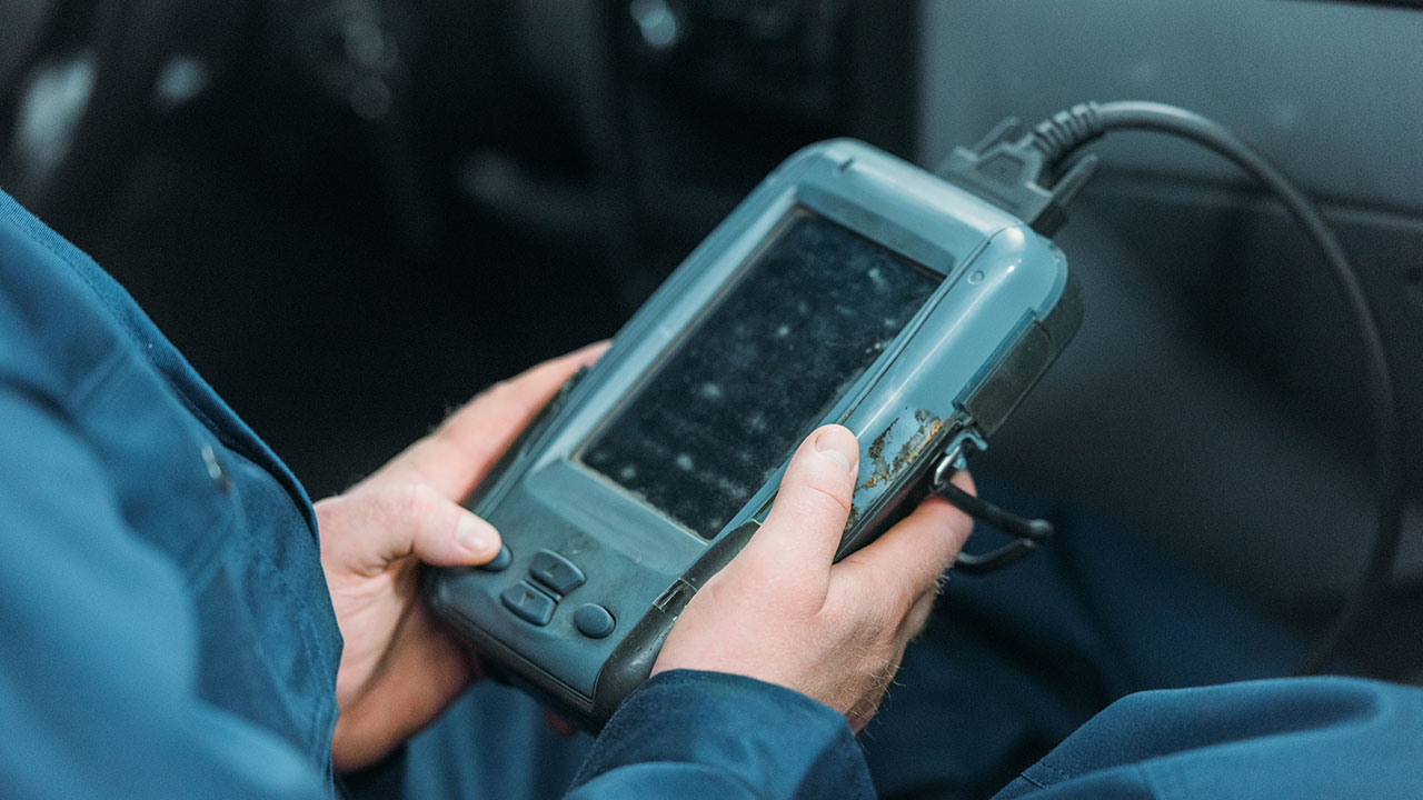
A damaged DLC does not always announce itself clearly. The failure modes can look like many other problems, which is why they get missed.
The most obvious sign is a scan tool that powers on but communicates with no module. When a scan tool shows power but no data, possible causes include a loose or corroded connector, damaged CAN high- or low-speed wiring, or jumper wires or splices from previous repairs that interfere with signal flow. Graham Collision
The less obvious sign is intermittent communication. The scan tool connects on some attempts but not on others. A tech does a wiggle test on the port, and the connection drops. That is a damaged crimp terminal connector or a broken wire inside the insulation that looks intact from the outside, one of the most time-consuming faults to chase if you do not start at the connector.
A third scenario is partial communication. The scan tool connects but cannot reach certain modules. This often points to a specific pin failure rather than a total loss, usually one of the CAN lines or a ground reference that is degraded rather than completely open.
The Right Way to Diagnose It
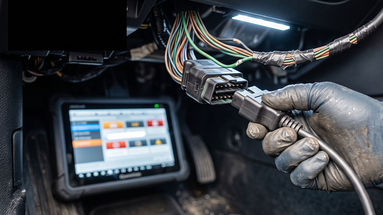
Before touching modules or pulling wiring diagrams on the CAN bus, start at the DLC with a multimeter.
Check pin 16 to chassis ground for battery voltage. Confirm pins 4 and 5 have solid ground reference, less than 0.1 volts drop to battery negative. An open circuit or high ground resistance on pins 4 or 5 means the PCM will never enter diagnostic mode regardless of what else is working correctly.
If power and ground check out, move to pins 6 and 14. These are the CAN lines. Look for resistance between them, a healthy CAN bus typically shows around 60 ohms across those two pins with the key off and modules powered down. A reading significantly higher or lower points to a wiring or module issue beyond the port itself.
If the pins show good values but communication is still intermittent, inspect the terminal seating inside the connector. Pulled or corroded terminals inside the DLC housing are a direct result of a car wiring harness that has been stressed, either from physical abuse at the port or from a damaged wire loom upstream that has allowed moisture to travel down the harness.
Repair vs. Replace: What the Job Actually Calls For
Once the DLC connector is confirmed as the problem, the repair decision comes down to how the damage presents. A single bent pin that can be carefully reformed without damaging the housing is a different situation from a connector with two broken locking tabs, corroded terminals on multiple pins, and a wire loom that shows heat or moisture damage behind it.
For a connector with physical damage to the housing or multiple terminal failures, a proper OEM-style wiring pigtail repair is the correct fix. Trying to reform bent pins or re-terminate individual wires inside a damaged housing is asking for an intermittent fault to come back. The DLC is too critical a connector to leave with a questionable repair. Every diagnostic procedure on that vehicle runs through it.
The types of wire connectors used in DLC repairs matter too. The crimp terminal connectors used on the replacement pigtail need to match the gauge and terminal style of the original circuit. An undersized crimp or a terminal that does not seat fully in the housing is the same problem as the one being fixed, just in a different location. This is not the place for generic butt splices or undersized heat shrink terminals from a bulk kit.
For collision shops specifically, the DLC is worth checking on any vehicle that has taken a hit in the lower dash area or has had significant interior disassembly. The port is located in an area that is disturbed during airbag replacement, lower dash panel removal, and steering column work. An auto electrical specialist catching a damaged DLC during teardown saves the shop a come-back diagnostic job after the vehicle is back in the customer's hands.
Why the Port Gets Overlooked
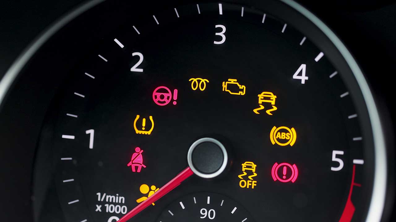
The OBD-II port works so reliably for so long that most techs never put it on a diagnostic checklist. It is not a component that shows up on a maintenance schedule. It does not throw codes when it fails. It just stops working, and the first instinct is almost always to suspect the scan tool, the modules, or the CAN bus rather than the connector itself.
That instinct costs time. Starting at the connector, checking power, ground, and terminal integrity before going deeper into the harness is the faster path in most cases.
The same lesson applies to any connector failure, not just the DLC. The fix is rarely complicated once the right connector is in hand. The hard part is finding it. That is the gap FindPigtails.com was built to close, covering hundreds of thousands of applications and helping techs identify the harder-to-source connectors most suppliers do not carry.
If you are dealing with a damaged connector anywhere on the vehicle, search by application at FindPigtails.com or send over a photo. The team will confirm the right fit before anything ships.